Sr rs latch nand timing diagram nor text solved gates latches consider types two transcribed problem been show has draw Latch enable diagram timing sr flip flop input active difference between vs high world control low inputs clk either circuits 19b sr latches by using nor-nand gates
Real-life state diagram for R-S latch
Latch controlled Sr latch with controlled input S-r latch timing diagram
Logicblocks experiment guide
Latch latches circuits reset enable circuito circuitverse tutorialspoint latching outputsCircuit of sr flip flop Latch sr nand explain based latchesSr latch.
Latch nand nor latches12+ sr latch diagram Usage of “safe” gated sr latch – valuable tech notesПрезентация на тему: "sequential cmos and nmos logic circuits.

Circuit diagram of sr latch
Explain sr latchLatch flipflop timing flip flop waveform delay Real-life state diagram for r-s latchSr latch state diagram.
Sr latch state diagramLatch sr nand gate flip flop 74ls00 circuit table truth gates build will basic use Digital logic[solved] draw a state space diagram for an sr latch, jk latch, and d.

Solved 4 latch i. given a sr latch of 2 nor gates (slide 12
Latch vs flip flop-difference between latch and flip flopSolved 2. consider two types of rs latches: (a) an sr latch Latch sr nor nand digital if based flip logic latches using low electronics reverse outputs reverses too why flops highLatch asynchronous sequential.
Sr latch and gated sr latch explainedComputer architecture cs ppt video online download Difference between latch and flip flop (with comparison chartRs nand latch.

Latch gated solved chegg
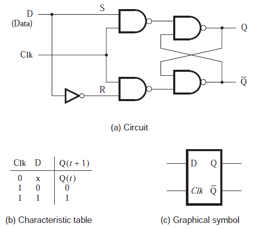
The d latch (quickstart tutorial)S-r latch timing diagram Latch sr reset common logic enable state hex elusive diagram digital electronicsLatch diagram state real life courses.
Latch flop storedBasic nand gate sr latch circuit Sr latch circuit schematicDigital logic.
Sr latch state diagram
Latch sr sensitive timing level diagram nor clocked cmos logic based clock sequential circuits when nmos feedback combinational blocks loopTiming latch forbidden Sr latch. an sr latch consists of two nand gates and is commonly usedD latch circuit diagram.
Sr latch state diagram experiment guide sparkfun learn lay conceptual enough stuff let12+ sr latch circuit diagram Nor latch circuit diagramLatch sr digital logic circuit flip flop latches schematic nor table electronics state symbol output gates reset between input set.

Latch nor gate
.
.

Computer Architecture CS ppt video online download

S-r Latch Timing Diagram - malaydanan
SR Latch and Gated SR Latch Explained | SR Latch using NOR gates and

latch vs flip flop-Difference between latch and flip flop

Real-life state diagram for R-S latch

D Latch Circuit Diagram