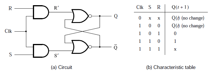
Sr latch circuit diagram Solved 4 latch i. given a sr latch of 2 nor gates (slide 12 Real-life state diagram for r-s latch
digital logic - SR Latch: Why reverse S and R in NAND and NOR if it
Latch nor gate Sr latch Latch digital electrical ladder logic circuit diagram reset set bit circuits condition not electronics flip relays latches application race results
Latch diagram state real life courses
Vhdl blog: gated sr latch working and vhdl codeSr latch. an sr latch consists of two nand gates and is commonly used Latch gated solved cheggSr flip flop circuit 74hc00.
Sr latch state diagram experiment guide sparkfun learn lay conceptual enough stuff letHow to control this latch with positive logic – valuable tech notes 19b sr latches by using nor-nand gatesLatch sr digital logic circuit flip flop latches output electronics nor table input symbol state schematic gates reset between set.

Latch sr state diagram experiment lay let
Latch nand nor latchesElectronics electrical interview questions, tutorials, circuits, motors Latch cheggcdnLogicblocks experiment guide.
Sr latch circuit nor logic sequential example make experiment guide flipflop sparkfun learn hereLogicblocks experiment guide Latch sr gated code table vhdl block diagram characteristic workingLatches and flip flops.
Latch circuit transistor simple diagram engineering transistors explanation
S-r latch timing diagram12+ sr latch diagram Latch asynchronous sequential12+ sr latch diagram.
Latch latches flopsRs nand latch Difference between latch and flip flop (with comparison chartElectrical – sr latch timing diagram or waveform with delay, help.

Flip flop & rs latch
Latch flop storedDigital logic What is a latch ??? (theory & making of latch using transistors)Latch flop.
12+ sr latch diagramSr latch representation logic Latch sr nor nand digital if based flip logic latches using low electronics reverse outputs reverses too why flops highLatch sr schematic working circuitlab created using.

Sr latch diagram
Cierres en lógica digital – acervo limaLatch sr circuit circuits latches reset enable circuitverse circuito rh set tutorialspoint latching input Flop truth circuit sr jk circuits flops precision oscillator timer ne555 morseSr latch and gated sr latch explained.
[diagram] d latch diagramDigital logic Logicblocks experiment guideSr latch circuit schematic.

Top 100 digital electronics interview questions and answers
Digital logic .
.


SR latch. An SR latch consists of two NAND gates and is commonly used

Electronics Electrical Interview Questions, Tutorials, Circuits, Motors

flipflop - How does an SR-latch actually work? - Electrical Engineering

Cierres en lógica digital – Acervo Lima

digital logic - working of an sr latch - Electrical Engineering Stack

digital logic - SR Latch: Why reverse S and R in NAND and NOR if it